
Logic gates are basic electronic circuits that perform Boolean operations on binary inputs (0s and 1s), producing a single output to make decisions in digital systems. They form the foundation of all computers, enabling everything from simple additions in calculators to complex AI processing in smartphones.
These binary inputs are nothing but electrical signals which come in two states i.e 0 and 1. We know that a computer runs on electricity. When a computer is turned on voltage pass through the circuits and they stay throughout the computer in two states. These two states are a binary variable that can be equal to 0 or 1.
Binary logic works with binary variables, which can only have a value of 0 or 1, and uses logical operations to process them. It helps describe how binary information is handled or transformed using algebraic expressions or tables. This processing is performed by logic circuits called gates. Gates are hardware components that produce a binary 1 or 0 based on the input conditions they receive. Digital systems use different types of logic gates, each with its own symbol and method of operation that can be explained using algebraic expressions. The behaviour of each gate, including how different inputs lead to different outputs, is usually shown in a truth table.
In computer systems, logic gates build ALUs for math, control units for sequencing, and memory for storage. For COA students, mastering them reveals how Von Neumann architecture executes instructions.
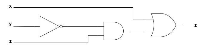
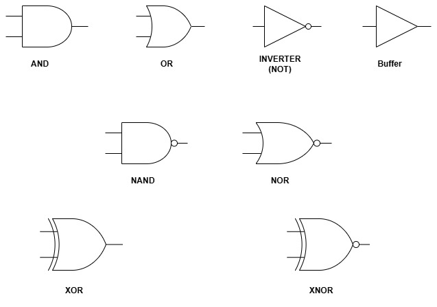
Let’s explore types with symbols, truth tables, and diagrams.
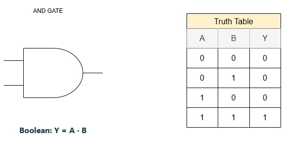
1. AND GATE
The AND gate performs the AND logic function, which means the output becomes 1 only when both input A and input B are 1. In all other cases, the output is 0. The algebraic symbol for the AND operation is the same as the multiplication symbol used in regular arithmetic. AND gates can also have more than two inputs, and the output will be 1 only when every input is 1.
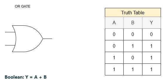
2. OR GATE
In the OR gate, the output becomes 1 if input A or input B, or both are 1. If all inputs are 0, then the output is 0. The algebraic symbol used for the OR operation is “+,” similar to the addition symbol in arithmetic. OR gates can have more than two inputs, and the output will be 1 as long as at least one input is 1.
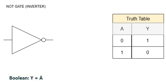
3. NOT GATE
In the NOT gate, the logic value of a binary signal is flipped. It performs the NOT, or complement, operation. The algebraic symbol for the complement is shown either by adding a prime mark to the variable or by drawing a bar over it. It is also known as an Inverter.
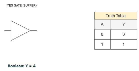
4. YES GATE (Buffer)
A YES Gate or the buffer does the opposite of an inverter. Instead of changing the logic value, it simply passes the input signal to the output without altering it. In other words, the output is the same as the input. Buffers are often used to strengthen a signal or to ensure that it can drive other circuits properly. In algebraic symbol, the output is represented exactly as the input.
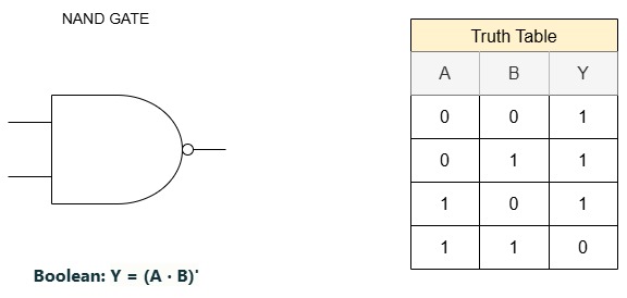
5. NAND GATE
The NAND function is simply the opposite of the AND function or its complement. The NAND gate gives a high output if any of the inputs are low. This is shown in its symbol, which looks like an AND gate with a small circle at the output to represent negation. The name “NAND” comes from combining “NOT” and “AND,” meaning it performs an AND operation and then inverts the result.
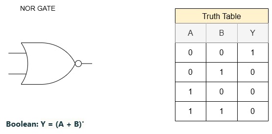
6. NOR GATE
A NOR gate is the opposite of an OR gate. Its symbol looks like an OR gate with a small circle at the output to show that the result is being inverted. Like NAND gates, NOR gates can also have more than two inputs. In every case, the output of a NOR gate is simply the complement of the OR function for the given inputs.
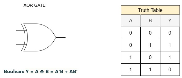
7. Exclusive-OR (Ex-OR) GATE
The Exclusive-OR gate, or XOR gate, produces an output of 1 only when its inputs are different from each other. This means the output is 1 when one input is 1 and the other is 0. If both inputs are the same, either both 0 or both 1 then the output becomes 0. The XOR gate has a special graphic symbol, which looks like an OR gate with an extra curved line on the input side. Unlike the regular OR operation, the XOR function highlights the idea of “either one, but not both.
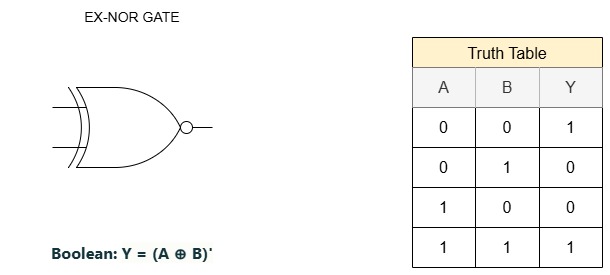
8. Exclusive-NOR (Ex-NOR) GATE
The Exclusive-NOR gate, or XNOR gate, is an Ex-OR gate followed by an inverter. It has two or more inputs and a output. The output of a two input Ex-NOR gate returns a high state if both the inputs are of same state. If the both the inputs are of different logic state then the output is low.