Decoders are key combinational circuits that take a compact binary code and “spread it out” into one active output line among many, which is why they sit at the heart of memory selection, display driving, and control logic. They are essentially the opposite of encoders and are fundamental in digital electronics and computer organization.
Decoders in Digital Electronics: Definition, Working, Truth Table & Uses
Contents
ToggleWhat Is a Decoder?
A decoder is a multi‑input, multi‑output combinational logic circuit that converts an n-bit binary input code into one of 2n possible output lines, such that only one output is active for each valid input combination.
In simpler words, a decoder takes a binary number at its input and activates exactly one output line corresponding to that number while keeping all other outputs inactive. This is why it is often described as performing the reverse operation of an encoder.
Basic notation and examples
An n‑to‑ 2n decoder has:
n input lines
2n output lines
Examples:
2‑to‑4 decoder (2 inputs, 4 outputs)
3‑to‑8 decoder (3 inputs, 8 outputs)
4‑to‑16 decoder (4 inputs, 16 outputs)
Decoders are widely used combinational circuits that convert binary inputs into a unique, human‑useful or circuit‑useful output pattern. They help a digital system “understand” encoded information and activate exactly one line or device among many.
Functions and Role of a Decoder
Interprets a binary code and selects one specific output line.
Ensures that, for a given input combination, only one output is HIGH (or LOW in active‑low designs) while all others remain inactive.
Acts as a code recognizer – it detects a particular input pattern and asserts the corresponding output.
Working Principle of a Binary Decoder
A binary decoder implements a direct mapping from each possible input to a unique output line using AND/OR/NOT gates. For an n‑to‑2n decoder with active‑HIGH outputs:
Each output is the logical AND of inputs (or their complements) that match one input combination.
Only one AND term evaluates to 1 for any given input.
Many practical decoders have an Enable (EN) pin:
When EN = 0 (disabled), all outputs are inactive (often all 0s).
When EN = 1 (enabled), the decoder functions normally.
2:4 Decoder
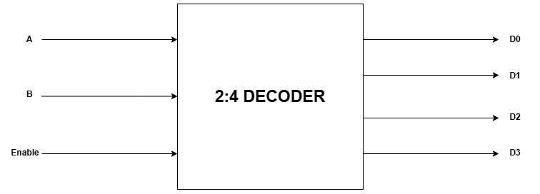
A 2:4 Decoder has 2 inputs and 4 outputs. Based on the 2 inputs , one of the 4 inputs are selected.

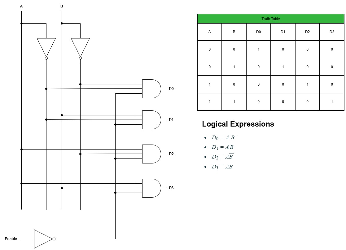
Logic Diagram of a 2:4 Decoder :-

3:8 Decoder
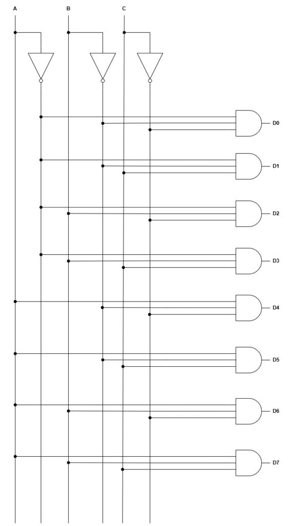
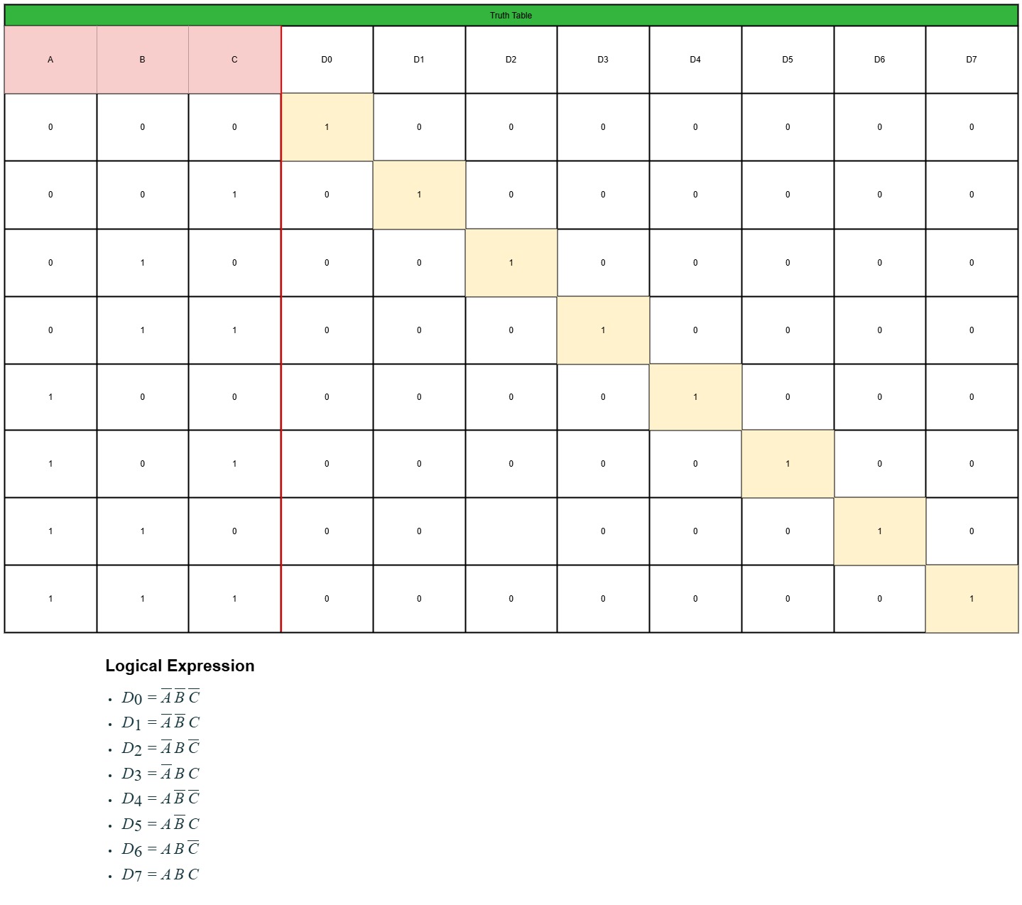
A 3:8 Decoder has 3 inputs and 8 outputs. Based on the 3 inputs , one of the 8 inputs are selected.

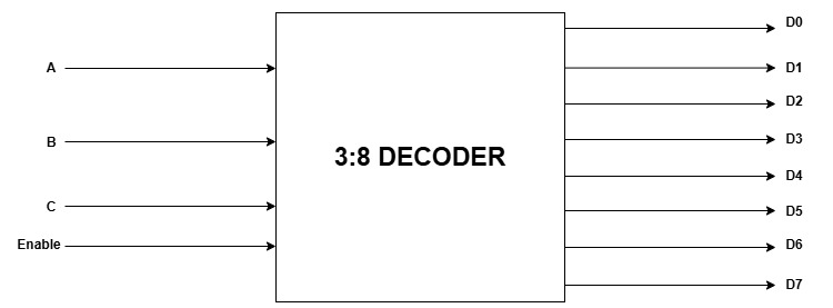
Logic Diagram of a 3:8 Decoder :-

Truth Table of 3:8 Decoder


