
A Boolean function maps inputs to output. For a given value of variables, the boolean function can either be 1 or 0. For example , we take the boolean function
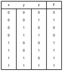
F = x + y’z
This can be also written as F(x,y,z) = x + y’z
This means:
F is a function of three variables: x, y, and z.
The output is calculated using the expression x + y’z.
The function F is 1 when x is 1 or both y’ and z are 1. Otherwise F is equal to 0. When we say y’ is 1 , it is equivalent to y=0, since y’ is the complement of y. So , we can say that F is equal to 1 when x is equal to 1 or yz is equal to 01.
This relationship between a function and its binary variables can be represented in a truth table and to represent the function, 2^n combinations need to be listed , where n is the binary variables. In this case , there are 3 variables : x, y and z. So 2^3, is equal to 8. Hence, the truth table will have 8 combinations.
A boolean function can also be represented in a logic diagram.
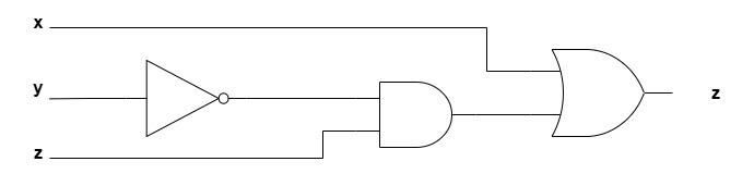
To understand the logic diagram for the function F = X + Y′Z, notice that the expression contains three basic operations:
Inversion (NOT) on Y, forming Y′
AND operation between Y′ and Z, forming Y′Z
OR operation between X and Y′Z, forming the final output F
Now these three binary variables are basically three inputs. In the expression F = X + Y′Z, the variable Y is first inverted to get Y′. This inverted signal is fed into AND gate with Z. The result, Y′Z, is then fed into OR with X. Therefore, the logic diagram includes an inverter for Y, an AND gate for Y′ and Z, and an OR gate that combines X with the AND output to generate F.
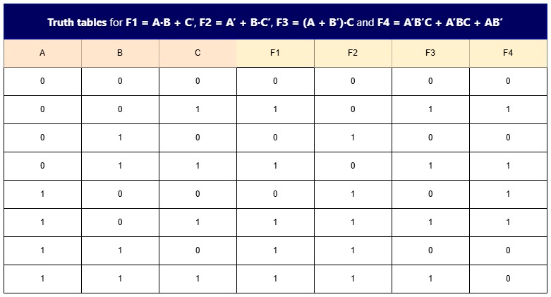
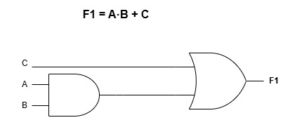
1) F1 = A·B + C
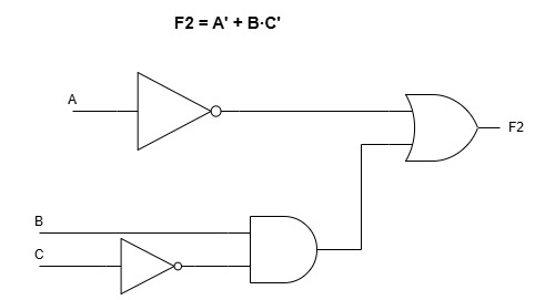
2) F2 = A’ + B·C’
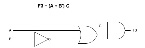
3) F3 = (A + B’)·C
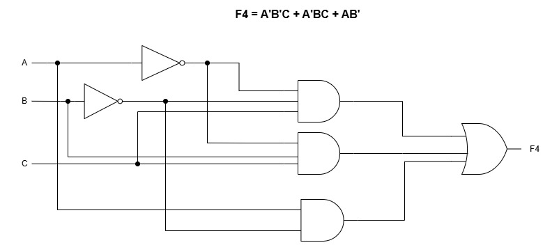
4) F4 = A’B’C + A’BC + AB’