
D Flip Flop ( or D Latch )
Contents
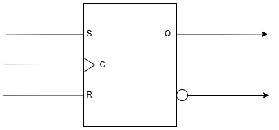
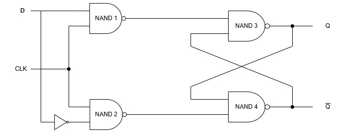
ToggleA D Flip Flop also called the Delay flip flop has two inputs. D and Clock inputs and two outputs Q and Q̅. A D Flip Flop is made from the SR Flip Flop by adding an inverter (NOT gate) between the S and R inputs of the SR Flip Flop and assigning D to the S input.
The normal SR flip-flop has two inputs. S (Set) and R (Reset).
We’re not allowed to give S = 1 and R = 1 at the same time, or the latch misbehaves. So the D flip-flop solves this by adding a NOT gate.
The input D goes straight to the S input
The inverted value D̅ goes to the R input
So:
If D = 1 → S = 1 and R = 0 → the flip-flop SETS
If D = 0 → S = 0 and R = 1 → the flip-flop RESETS
This means the SR flip-flop never receives an illegal “1,1” combination making it a new Flip Flop named D Flip Flop.
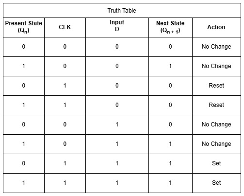
From the truth table of the D Flip Flop , it is clear that whenever the clock input is low, the flip flop stays in its present state. ( Qn = Qn + 1 ).
Whenever the clock is high , irrespective of the value of D, it will always be equal to Q. ( D=Q ). When D is 0 , Q is 0 (Reset) and when D is 1 , Q is 1 (Set). In D flip flop transfer of data is delayed and hence it is called a Delay Flip Flop. The D flip flop is either used a delay device or as a latch to store a 1 bit of information.