Encoders are the opposite of decoders. Instead of expanding a binary code into many lines, they compress several input lines into a shorter binary output code.
Encoders in Digital Electronics: Definition, Working, Truth Table & Uses
Encoders are core combinational circuits that convert multiple input lines into a compact binary code at the output. They are used whenever a digital system needs to know which one of many lines is active and represent that information as an nn-bit binary number.
What is an encoder ?
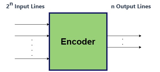
An encoder is a combinational logic circuit that converts up to 2n input lines into an n-bit binary output code, assuming only one input is active at a time.
In simple terms, it encodes the position of the active input line into a binary number on the outputs. For example:
A 4‑to‑2 encoder has 4 inputs (D₀–D₃) and 2 outputs (Y₁Y₀).
An 8‑to‑3 encoder has 8 inputs (D₀–D₇) and 3 outputs (Y₂Y₁Y₀).
Key properties
Typically 2n inputs and n outputs in a simple binary encoder.
Inputs usually active‑HIGH (logic 1 means “selected”).
Output represents the index of the active input in binary.
Block Diagram - Encoder
Functions and Purpose of an Encoder
Encoders perform three main roles:
Code conversion: Convert a one‑hot or decimal‑like input into binary code.
Data compression: Replace many wires (parallel signals) with fewer binary lines.
Source identification: Indicate which device, key, or sensor is active.
This is the opposite of a decoder, which takes binary and activates one of many lines.
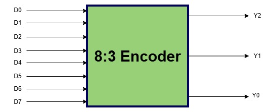
8:3 Encoder
A 8:3 encoder has 8 inputs and 3 outputs. It accepts eight inputs and produces 3 bit output code, corresponding to the activated input. It is also known as Octal to Binary Encoder.
8:3 Encoder Block Diagram
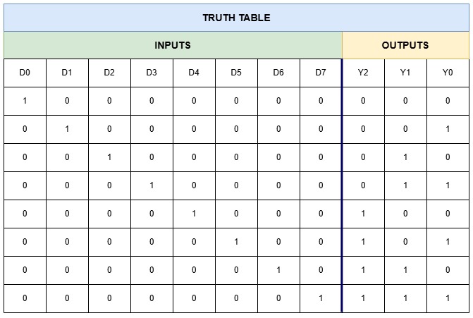
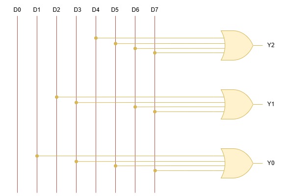
Working of a 8‑to‑3 Binary Encoder
An 8‑to‑3 encoder has inputs D0–D7 and outputs Y2,Y1,Y0. If only one input is HIGH, then
Spread your knowledgeIntegrated Circuits Integrated Circuits (ICs) are used to manufacture Digital Components. Integrated Circuits pack thousands to billions of […]
Spread your knowledgeBoolean Algebra Boolean algebra manipulates binary variables (0/false, 1/true) using AND, OR, NOT to design digital circuits. It […]